To evaluate voltage unbalance we can use Symmetrical components method proposed by Charles Fortescue. Vector of three phase voltages can be expressed as a sum of three vectors (phasors): zero- positive- and negative-sequence.
\[ U_{abc} = \begin{bmatrix} U_a \ U_b \ U_c \end{bmatrix} = \begin{bmatrix} U_{a,0} \ U_{b,0} \ U_{c,0} \end{bmatrix} + \begin{bmatrix} U_{a,1} \ U_{b,1} \ U_{c,1} \end{bmatrix} + \begin{bmatrix} U_{a,2} \ U_{b,2} \ U_{c,2} \end{bmatrix} \] \[ \alpha \equiv e^{\frac{2}{3}\pi i} \] \[ \begin{align} U_{abc} &= \begin{bmatrix} U_0 \ U_0 \ U_0 \end{bmatrix} + \begin{bmatrix} U_1 \ \alpha^2 U_1 \ \alpha U_1 \end{bmatrix} + \begin{bmatrix} U_2 \ \alpha U_2 \ \alpha^2 U_2 \end{bmatrix} = \ \end{align} \] \[ \begin{align} &= \textbf{A} U_{012} \end{align} \]
From these phasors we can derive negative-sequence voltage unbalance ratio K2U and zero-sequence voltage unbalance ratio K0U
\[ K_{2U} = \frac{U_2}{U_1} \] \[ K_{0U} = \frac{U_0}{U_1} \]
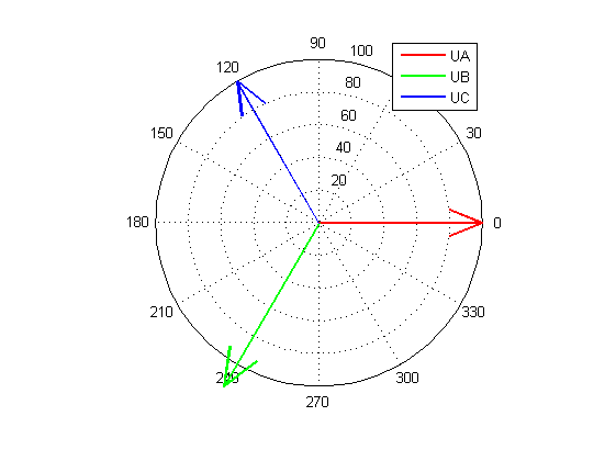
Here is MATLAB script that produces the desired level of both negative- and -zero voltage unbalance ratio, then sets respective phasor magnitudes. After that we estimate unbalance using Symmetrical components method and draw a phasor diagramm.
1 2 3 4 5 6 7 8 9 10 11 12 13 14 15 16 17 18 19 20 21 22 23 24 25 26 27 28 29 30 31 32 33 34 35 36 37 38 39 40 | |
To generate signal with known level of unbalance $K_{2U}$ we can change magnitude of one of the voltages in the balanced three phase system. So we set all angles between voltages = 120 deg. Magnitudes of Ua and Uc should be equal (Ua=Uc). Ub should be set as
\[ U_b = U_a \frac{1+2 K_{2U} }{1-K_{2U}} \]
This equation can be easily derived if we notice that
\[ U_1 K_{2U} = \frac{1}{3} (U_b + 2 U_a) K_{2U} = \frac{1}{3} (U_b - U_a) = U_2 \]